Hacking the NDP Pixmob bands - How I got the LED band to run my code
Wed, May 17, 2017NDP 2019: My friend Kheng Meng has already documented about the 2019 edition, even before the official event. Check it out!
The NDP 2016 Pixmob band - thousands mesmerized, documented by many, but still not hacked to run custom code.
This (fairly lengthy) post documents how I learnt about the ISP protocol, built a board to implement it and integrated it with the Arduino IDE.
The Pixmob band
Within the milky plastic enclosure lies a compact board comprising of
- IR Sensor (38KHz)
- Vibration sensor switch
- RGB LED
- I2C EEPROM (AT24C02S)
- ABOV MC81F4204
- CR2032 battery (~3V)
Everything listed is available as a jellybean part except for the very unusual MC81F4204,
The ABOV (MC)81F4204
“8-bit MCU, 4KB Flash, 192B RAM using a custom architecture (“810 Core”)”
Takeaway: difficult to source, ancient proprietary IDE, requires a special programmer
Also: No UART. 192 bytes of RAM
Searching online for a hardware ISP (and failing)
Finding a means to interface with the chip (for example, to read the chip ID, or even the firmware) would be a great first step towards the ability to write a new firmware. I wasn’t alone in this hunt, but this turned out to be lengthy and fruitless.
The datasheets had nothing on the programming protocol. Use their programmers, they said - except I found out later that it was no longer available for sale.
Emailing Chinese vendors was without avail, and the only listing on Aliexpress was “no longer in stock”.
Nested within ABOV’s Chinese-only site was a Taobao listing, but at 1000 Yuan (~S$200), it was out of my budget.
Lior Elazary KK6BWA published a guide on programming the MC81F8616. Having a guide, especially for the MC81 family was an exciting lead, but it turned out that his code just didn’t work for the 81F4204.
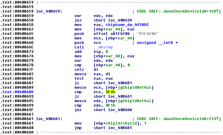
Reversing ABOV’s ISP software did not yield much, as the logic and timing was stored in the programmer hardware itself. It did reveal the 81F4204’s ChipID (0xF0 or 0xF1), confirming that Lior’s tools could not work.
The breakthrough - Visiting ABOV’s Seoul HQ

On a trip to Seoul, I took a detour on the subway, across the Han river, into the swanky business district of Samseong to find ABOV’s Seoul HQ.
I was half expecting to be Broadcom’d but instead was surprised with their generous hospitality and help!
They advised me that..
- The MC81F4204 is an end-of-life product
- MC81F4204 ISP tools are no longer made or in stock. (I tried to buy their ISP right there)
- MC81F4204 has a silicon error that severely limits the number of flash-writes before failure
- Their “fuse bits” are stored in the flash. Failing to write the original data back after a flash erase will brick the chip
- Only one (ancient) IDE is available unlike their other offerings which worked with KEIL.
- They had 32-bit ARM product line, and to try it!
They quickly linked me up with the right department anyway and provided publicly unavailable documents for the 81F4204 - complete with documentation on the programming process!
Their assistance and transparency, especially to a “typical civilian” (as opposed to huge corporations) was a pleasant surprise and I would definitely recommend them.
Implementing an ISP with a datasheet
This is documented in 2 parts - building the ISP hardware, and its corresponding firmware.
ISP Hardware
The hardware end of the programmer requires
- Serial Data (SDA)
- Serial Clock (SCL)
- Programming Power (VPP)
- 5V & GND
VPP, a 9V signal held on the reset pin, is used to enter programming mode, and is likely used to erase the flash memory. The other pins operate at 5V TTL levels.
With these criteria, I chose to implement the programmer as a board to stack on the Arduino Pro Micro. The ProMicro operates at 5V, has native USB, is well documented and can be had for US$2.90 shipped.
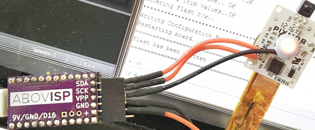
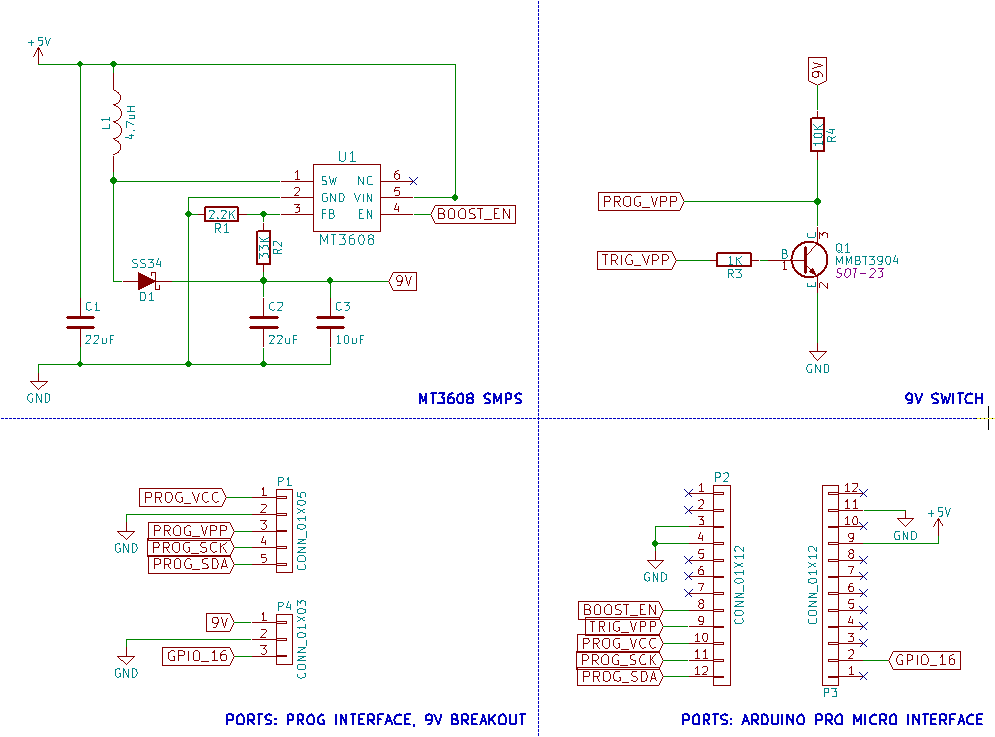
Introducing.. the ABOVISP!
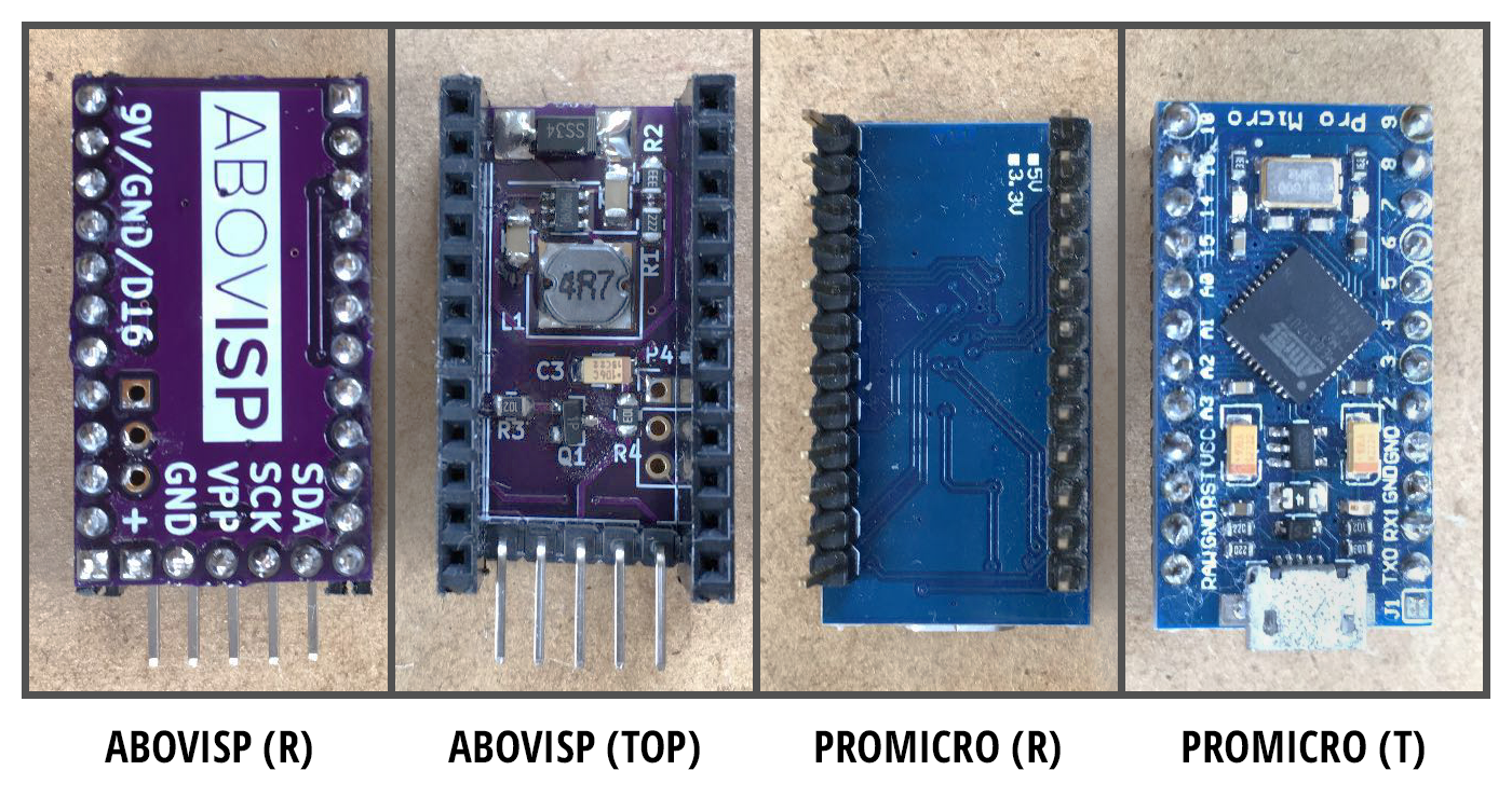
The board is open source (KiCAD), designed with cost in mind and uses exclusively Chinese jellybean parts. These are my favourite and work great as long as you severely de-rate them.. and can wait a month for shipping.
The MT3608 is a step-up switchmode power supply to generate 9V from USB’s 5V, and operates at 1.2MHz! I reworked the chip with its associated components from a generic board via hot-air.
BOM (Should cost below $15 USD including shipping):
- PCB from OSH Park. ($4.25 / 3pcs)
- Arduino Pro Micro ($2.90 / 1pcs)
- MT3608 generic board ($1.10 / 1pcs)
- 4.7uH CD32 Inductor ($1.02 / 25pcs)
- MMBT2222 / MMBT3904 or similar ($1 / 100pcs)
- 0805 Resistors 2.2K, 33K, 1K, 10K ($2 / huge assortment)
ISP Firmware
The Arduino implements the timings and logic to interact with 81F4204, starting with primitive functions to send and receive bytes.
Communications are made through an SPI-like protocol with a bidirectional SDA pin (instead of MISO/MOSI), as well as an extra clock bit at the end of every byte. Higher level functions like address reads, flash writes are then built on top of this.
The Arduino-PC communication is performed over a USB virtual COM port, and is accessed on the PC as a serial port with any baud rate. The protocol is simple:
[Fuse Byte / Option value]{4096 ASCII-encoded bytes}
The “blink test” firmware which I usually copy from Notepad and paste into the Arduino Serial Monitor looks like..
[24]{601E001B.. snip ..F022F022F022F022F022F022F022F000F0}
With this, it is possible to write a new firmware to the board. Onto building our own firmware!
Building a firmware
Getting a toolchain
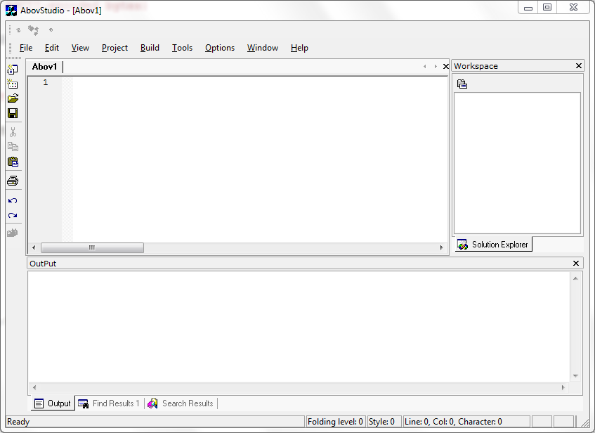
AbovStudio is the official (and only) development software available for the 81F4204 and 119 other ABOV microcontrollers.
The 29MB package contains the IDE, compiler (what appears to be an old, modified gcc), microcontroller-specific configurations and samples. Installing it places a fixed HMS800 folder in your C:\ and adds it to the system PATH. Thankfully no drivers or new startup items are added.
Using AbovStudio proved to be cumbersome, however its build process simply generates a batch file and runs it, emitting map/lst/out/hex files. With this in mind, I was able to write using Sublime Text and run the batch file to compile.
Blink - the hardware “hello world”
Getting a microcontroller to blink usually involves these steps:
- Initialize the pin connected to the LED as an output
- Set the LED pin as either HIGH or LOW
- Idle for some time (delay)
- Set the LED pin as either LOW or HIGH
- Idle again
- GOTO 2
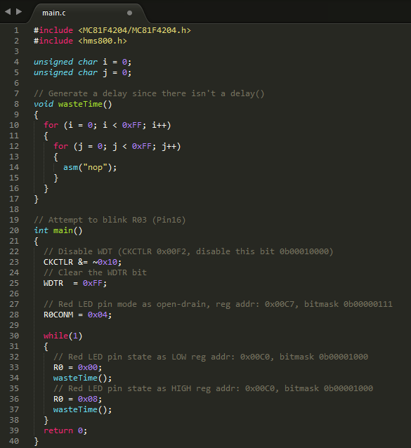
There were some additional steps to make it work here: The 81F4204 has a built-in watchdog timer which resets the microcontroller if it has not been “fed”. This would be useful to prevent deadlocks and crashes, but for simplicity, I chose to disable the WDT at the start.
There was also no delay() available unlike the Arduino. The wasteTime() is implemented to unroll 2 adjustable loops calling the no-operation opcode, essentially doing nothing for a fixed period.
Compiling involves running the batch files containing 3 lines:
hms800-cc -ramclr -mshort -Os -g -Wa,"-mhms800" --option-file=C:\HMS800C\options\MC81F4204.opt -Wa,"-ahls=.\main.lst" -c -o .\main.o .\main.c
hms800-cc -ramclr -mshort -Wl,"-Map=.\main.map" --option-file=C:\HMS800C\options\MC81F4204.opt -o .\main.out .\main.o
hms800-elf-objcopy -O srec .\main.out .\main.hex
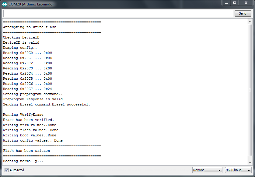
On completion, the firmware in S-Record format is placed in the same folder with the .hex extension. Parsing it and uploading via ABOVISP results in having the red LED blink! Woohoo!!
Porting it to the Arduino IDE
Disclaimer: it’s hacky. Avoid using it in anything serious.
Arduino IDE is a known starting point for many, and recently it made available features to support custom boards and processors.
For the end-user, the Arduino “language” offers helpful high-level functions and syntactic sugar in a consistent manner across microcontrollers, while allowing access to lower level C functions. Instead of toggling bits on an entire port to change its state, helpers like pinMode and digitalWrite along with aliases such as PIN_LED_RED step in to make it much easier and readable.
Supported Arduino features
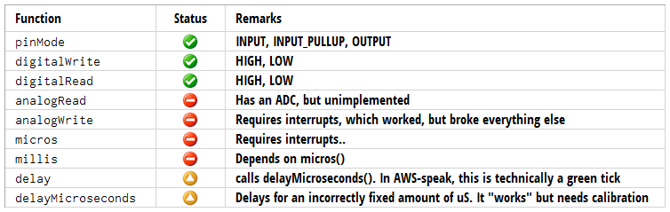
Thank you AWS for the lovely icons.
The port has its fair share of shortcomings, but works for basic applications. The crippling issue with developing for the MC81F4204 is the flash-write corruption, which subtly manifests itself as buggy code until it is verified by uploading a known good firmware and observing that it still does not work. I’ve already blown through about 6 Pixmob boards to come up this entire project, and estimate an average of 10 flashes before the board exhibits this issue.
The porting process: Recipes
Adding new hardware to arduino involves creating the necessary folder structure and configuration files (platform.txt, boards.txt and programmers.txt). These files follow a key=value format.
boards.txt
Boards will contain menu listings for different board variants, its associated upload tool, core, memory and can also include custom parameters such as microcontroller-specific fuse bits.
platform.txt
Platform contains microcontroller-specific settings, such as path and parameters to be used during compilation, linking, uploading, and the sketch’s memory use. The commands that Arduino IDE will run during compile/upload are called patterns and they can also supply upload-specific parameters such as the temporary compilation folder path.
programmers.txt
This was not used (blank).
abovflash.exe : The glue to pull everything together
Pressing Upload on the Arduino IDE performs a series of actions:
- Saves the active sketch
- Creates a temporary folder in
%LOCALAPPDATA%\Temp\arduino_build_*and copies the sketch into it - Runs its own arduino-builder. I’ve no idea what this does but it seems to be for caching
- Runs recipe to detect libraries used and generate ctags
- Runs recipe to compile
- Runs recipe to determine compiled firmware’s memory use
abovflash.exe is a C# binary that fits into this by having recipes transfer essential parameters to it and..
- Locates the temporary sketch folder and generates a dummy ctags file
- Merges the sketch with a custom header that implements all the arduino-esque features
- Calls the HMS800 (Abov DevStudio) compiler to build the preprocessed file
- Parses the emitted S-Rec firmware, or throw an error if there isn’t one (compilation failure)
- Saves
firmware_size.txtas Arduino will later request for the built firmware’s memory use - Saves
firmware_command.txt, a text file containing the firmware string and calculated fuse bits to be sent to the serial. - If upload is required, open the specified serial port and send the firmware
Usage
Install
- Arduino 1.8.2 (minimum version)
- Abov DevStudio
- Extract the
abovfolder into%USERPROFILE%\My Documents\Arduino\hardware - Launch Arduino IDE, Connect Arduino ProMicro and upload ISP firmware
- Under
Tools>Board, PickABOV G810. ThePortremains unchanged
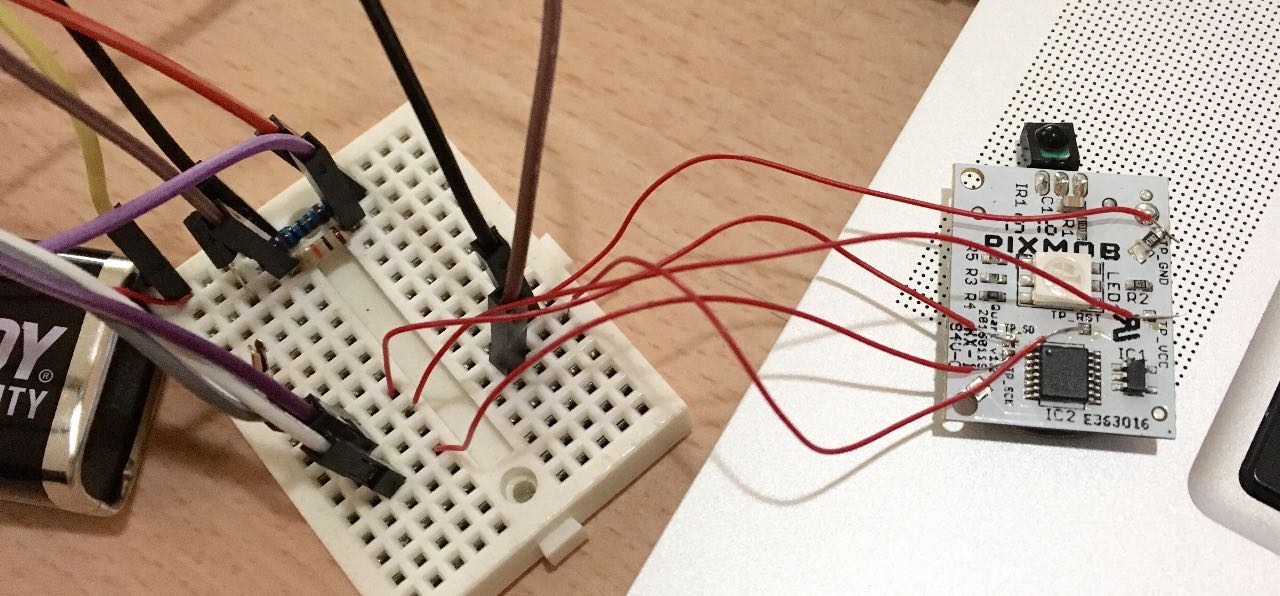
Connect:
- Pixmob
TP_SDto ABOVISPSDA - Pixmob
TP_SCKto ABOVISPSCK - Pixmob
TP_RSTto ABOVISPVPP - Pixmob
TP_GNDto ABOVISPGND - Pixmob
TP_VCCto ABOVISP+
I prefer using the battery tabs and ground plane instead as the Pixmob’s test points are small.
Upload:
When you are ready, hit Upload and it should automatically compile and upload. The Pixmob board’s LED will turn green during the upload process. Have fun!!
Diagnose:
To diagnose if the flash has permanently failed, open KnownGoodFirmwareBlinkAll.txt and paste the contents into the Arduino Serial Monitor to trigger a manual upload. The LEDs are expected to blink in sequence.
Examples!
If everything works, the examples are a great way to try programming the 81F4204! Also included with the Arduino bits on github
Impact Sensor
abovExampleImpactSensor.ino
Powers on and stays green until an impact event, where it turns red until poweroff. Ideally the device should not break apart.

Infrared Detector
abovExampleIRDetector.ino
Indicates presence of ~38KHz IR transmission with red LED. Easier than staring through the phone camera.
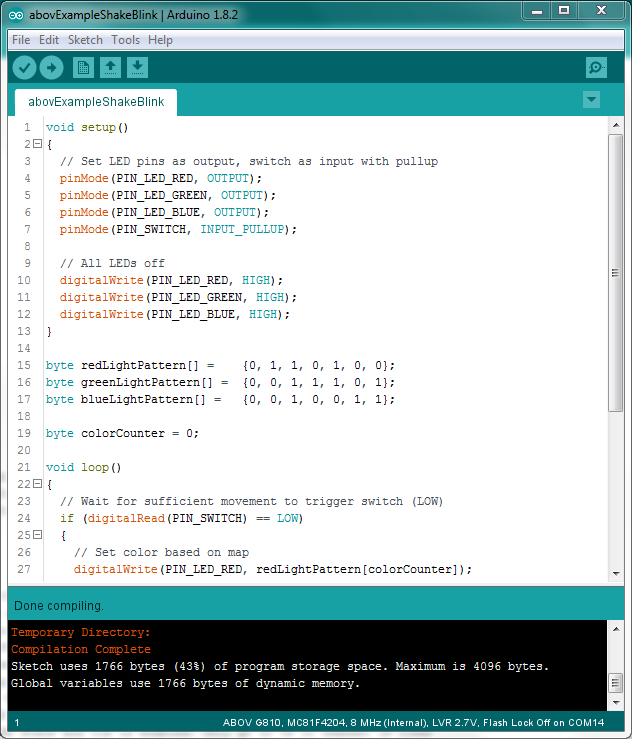
Shake To Blink
abovExampleShakeBlink.ino
Shake to blink. Instant rave party!
Why all these?
During the NDP when I first saw this, it seemed like a promising platform for kids to learn programming - from my understanding, almost all Primary 5 students attend the show, and should also receive a Pixmob band. In an ideal world, this could have been another micro:bit. However, the limited flash life and lack of self-programming features leaves this as a no-go : (
Having done all these, I found it an incredibly fun journey! I’d be glad to loan out my ABOVISP to a hacker/makerspace here (Singapore!) if there are any takers ^_^
What’s next
I initially planned to dump the firmware via glitching too. However I do not have the requisite hardware so that remains to be done.
I also looked into decapping the chip but the requisite solvents are also.. hard to source.
The published code will be as-is and unmaintained. Most of my boards are dead..
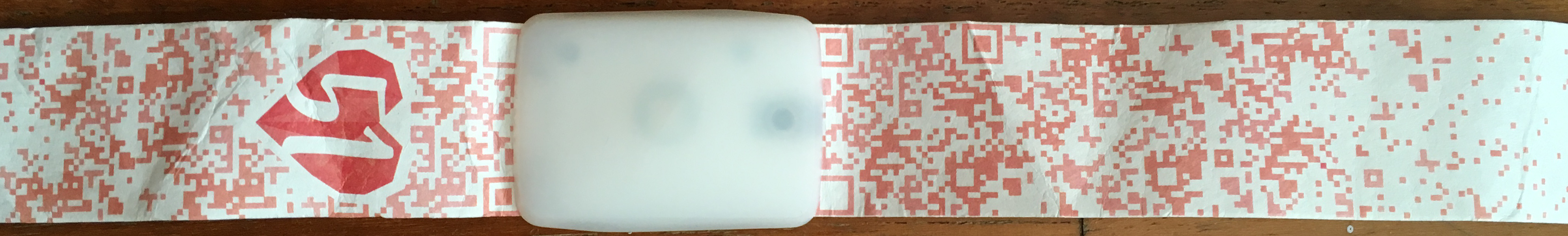
Trivia
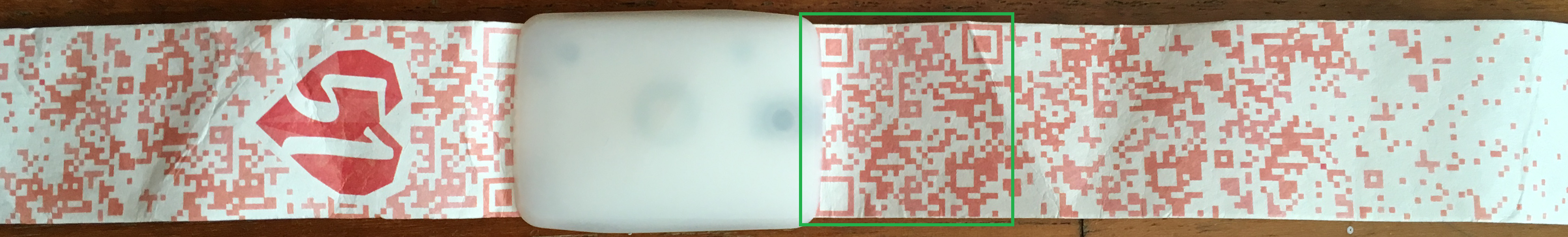
The band’s straps contains QR-like decorations but it seemed too coincidental. The right end of the Pixmob device has a malformed QR code on the strap, and transforming and restoring the QR reveals this:

Bottom-right square border was originally missing the inner square, restored here
Scanning it leads to a defunct site at http://www.seagames2015.com/ (valid WHOIS) which, less surprisingly, used Pixmob bands too!
That’s all for now! Thanks for reading through!